Brake Bracket
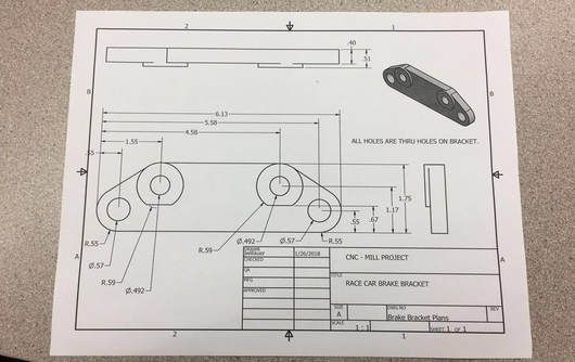
Our goal was to create this exact brake bracket in Inventor. After it was modeled in Inventor we need to use the Mill to create a 3D tangible version of the bracket.
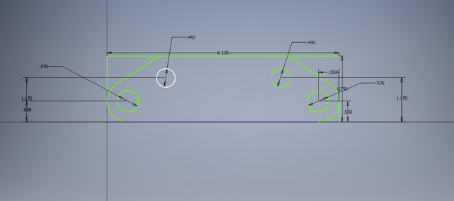
Mrs. Proctor said we should be able to create this bracket in 2 sketches. As you can see my first sketch is shown on the right.
I started with the correctly dimensioned rectangle. Then I added the four circles. I then added circles around the original circles to make them look like a doughnut.
Once that was done I used the line tool to connect the circles to the outer edges and then used the tangent constraint to make sure they all aligned up with one point. Finally I cut all the unnecessary lines out so it looks like the picture on the right and then extruded the entire sketch .40 of an inch.
|
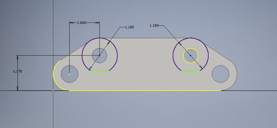
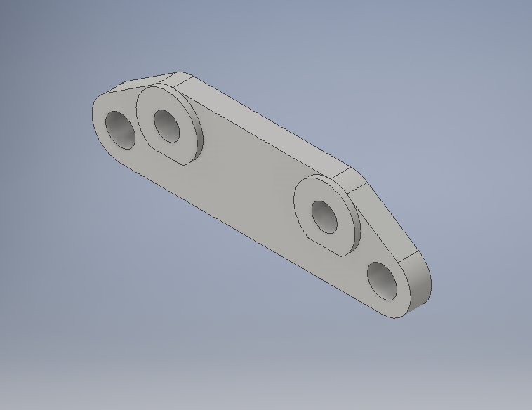
For my second sketch I drew in the circles for the raised part of the bracket. I finished the sketch and extruded the two circles .11 of an inch. It should look like the picture on the right.
|
|
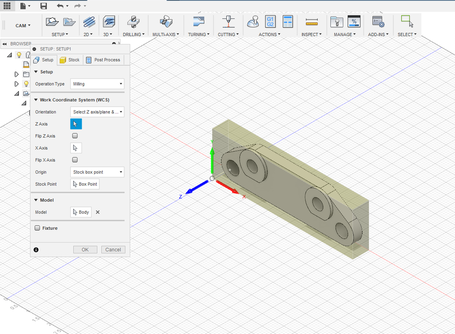
Once I had my brake bracket modeled in Inventor, I loaded it into Fusion 360. After setting the stock and box point to the lower corner, I chose my axes for this project and hit okay.
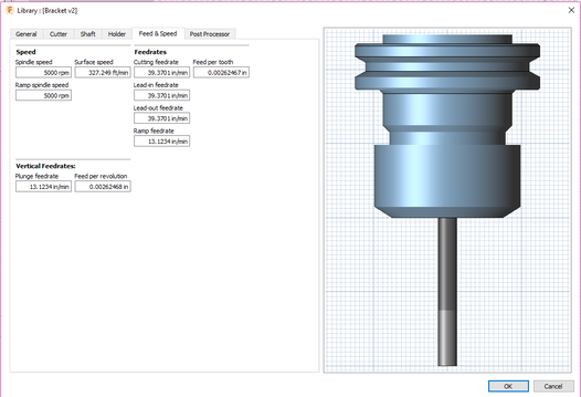
Next, I changed my drill bit and spindle speed for the CNC Mill. The spindle speed for the mill is 5000 RPM and the feed rate is 39. Once my bit is changed to the machines features I hit okay.
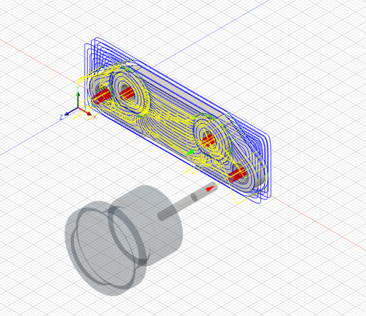
This is a picture of my tool paths. Based on my simulation the mill will cut out my circles first then cut out the bracket.
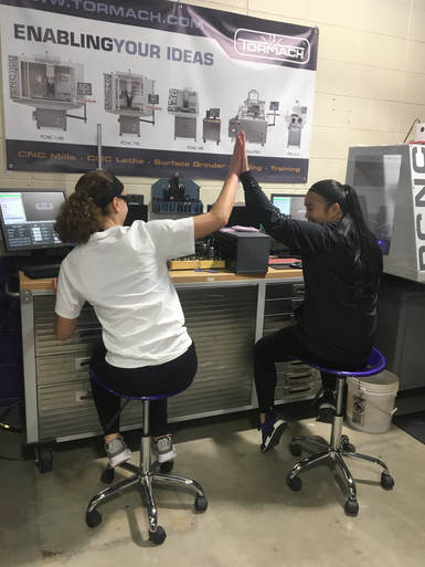
This is a picture of Caitlyn and I setting up our brake brackets on the CNC Mill. As you can see we're both super excited to be using this fancy piece of tech.
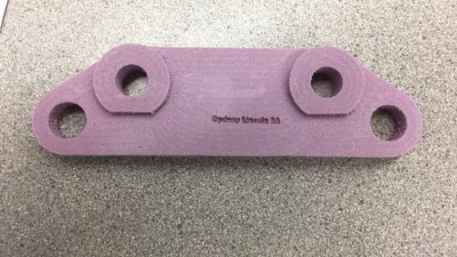
This is my final product. Like our maze we had to engrave our name on our bracket.
Summary
In this sub unit I learned how to read and interpret a blueprint for a real life application. At the beginning of the project we were given a dimension sheet and we were required to design the bracket on Inventor. While working in Inventor I learned how to use the tangent tool. This tool lined up the line segment and the circle of the brake part.
In addition to the new Inventor tool I also reinforced my new knowledge of Fusion 360. For the maze we had to use the 2D contour but for the break bracket we had to use the 3D contour.
In addition to the new Inventor tool I also reinforced my new knowledge of Fusion 360. For the maze we had to use the 2D contour but for the break bracket we had to use the 3D contour.
