My Maze
Design Idea
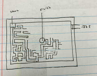
This is a picture of my maze ideas in my engineering notebook.
Inventor
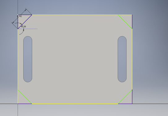
I started out by extruding my basic shape, a rectangle. Then I extruded out all four corners at a 45 degree angle. I wanted to change things up a bit so I decided to add some handles to my maze. I started by extruding a rectangle then added semi circles to both ends and then filet the edges.
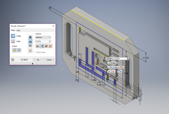
After my handle edges were filed I started making my maze components. As you can see in the picture the circle in the center is the finish and the square in the top left corner is the start. I drew rectangles .313 in width all around my space. Once a good chunk was drawn I extruded .125 of an inch inwards.
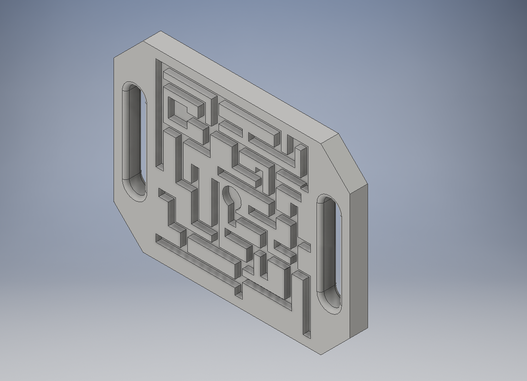
I continued drawing my maze until it was finished. Make sure all your components are .25 of an inch away from each other so the integrity of the walls don't brake. This is what my completely extruded interior maze looks like.
Fusion 360
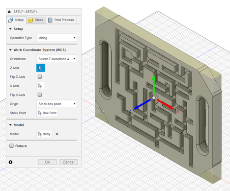
Once everything is where I want it you can open up Fusion 360. First thing you need to do is upload your Illustrator file. After your file is open you need to change the sculpt button to CAM, don't forget to switch your units too. Next you need to make sure your orientation is correct. It should look something like the picture to the right.
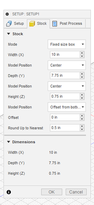
When your orientation is correct you can find the Stock tab. Under this tab you will need to change the width, depth and height of your maze. Once the dimensions are fixed find the the offset feature and set it to 0.
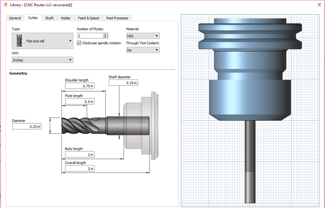
Now we are going to set up the path of the machine is going to follow. For this project you will use the 2D contour. Click on tool and select a flat end mill. Change the diameter to .25 in and the body length to 2 in. Click on the feed and speed tab and change the spindle speed to 10000 rpm and the cutting feed rate to 200. Under the passes tab you need to change your max rough step down to .25 in and your stock to leave to 0, then hit okay.
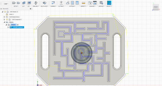
Once all your set up is complete you need to simulate your tool paths to be sure they are correct.
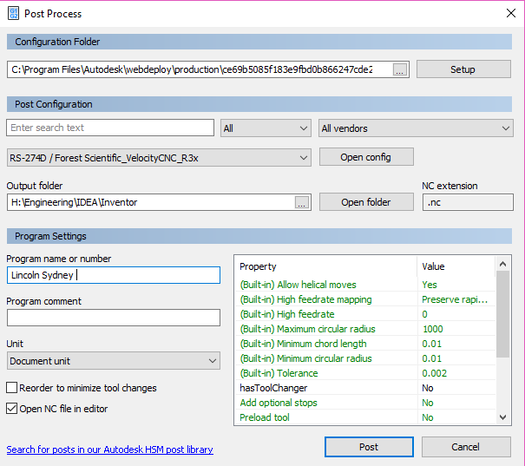
Once you get your simulated tool path approved you can go ahead and export the file in "GCode". This is the code that is compatible with the router.
Once your "GCode" is exported you can download a copy onto your flash drive and head down to the router.
Once your "GCode" is exported you can download a copy onto your flash drive and head down to the router.
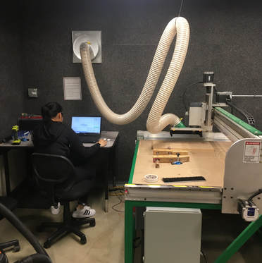
This is a picture of me setting up my router.

This is a picture of my print.
The final step was to laser engrave my name on my maze. I made a file on illustrator changed the lines to .0001 and made sure my lines were 100% pure blue. If you don't make the blue 100% blue your foam will melt. Once you get down to the laser you need to change the speed to 100% and the power to 14%. When you've set your laser in the location you want it you can hit the green button.
The final step was to laser engrave my name on my maze. I made a file on illustrator changed the lines to .0001 and made sure my lines were 100% pure blue. If you don't make the blue 100% blue your foam will melt. Once you get down to the laser you need to change the speed to 100% and the power to 14%. When you've set your laser in the location you want it you can hit the green button.
Summary
This unit has been the most frustrating unit so far. This was the first unit where I had to either start over and reverse engineer my problems. However, this has been the unit where I have learned the most. I learned how to use Fusion 360 to turn an Inventor file into a file compatible with the CNC Router and CNC Mill. I also learned that out of all the engineering programs this class uses Fusion 360 is the most difficult to navigate. There are lots of tiny detail steps that are crucial to your project that you need to do before you can actually get to using the router or the mill.
